
Updated on 29 May 2025
Interested in building web applications consisting of multiple servers (VMs, Bare Metal or some combination of the two)? Want to minimise downtime caused by an outage of one part of the system? While it might not be possible to provide a single ‘one-size-fits-all’ solution, we’ve put together some helpful insights into the underlying infrastructure and some practical advice so that you can deploy your own applications in a more robust fashion.
What is the CloudNX architecture?
CloudNX is designed with a modular architecture. Essentially, that means that there are different building blocks called Availability Zones (AZs) inside each data centre, plugged into a core network. The core networks are plugged into the global backbone network which interconnects the data centres.
Introducing Availability Zones (AZs)
Mentioned above, an Availability Zone comprises a set of infrastructure (hosts, switches, firewalls). If you have multiple servers in the same AZ, there’s a chance that they share a common component.
For example, perhaps you have two Bare Metal servers connected to a common top-of-rack switch. Of course, the top-of-rack switch has redundant connections to an aggregation layer but it’s still a single point of failure (SPoF). Or maybe you have two Cloud Servers that are sharing a physical host. Even if your setup uses a combination of Bare Metal and Cloud Servers, they could be sharing a common firewall.
The AZ feature allows you to make sure that your servers aren’t sharing any of these components. So, a server in AZ1 can’t share a host, top-of-rack switch or firewall with a server in AZ2. The core infrastructure is still shared, but this is all resilient, redundant and generally stateless so is less likely to fail.
We recently exposed the AZ concept to customers so you can now see which AZ your servers are currently deployed in and can select which AZ new servers are deployed into.
Let’s look at failure domains
When designing with high availability in mind, it’s important to look at what failure modes we’re trying to mitigate. It can be helpful to consider what SPoFs (single points of failure) exist in the infrastructure, and view the infrastructure in terms of failure domains.
A failure domain is the infrastructure which is inside the blast radius of a particular failure mode e.g. the failure domain for a top-of-rack switch outage would be the servers in that rack. The failure domain for a catastrophic event (earthquake, fire, nuclear explosion etc) could be an entire DC.
The first example could be avoided by making sure your servers are deployed in different AZs (different AZs means different top-of-rack switches). And effects from the second example could be reduced by deploying your servers in different DCs. Depending on your application requirements, the first (more likely) failure is probably easier to mitigate.
It’s also worth bearing in mind that as you increase the complexity of a system (like adding multiple layers of redundancy), you can actually decrease the resilience of it. This is down to the increased risk of human error, unanticipated failure modes and increasing MTTR (Mean Time To Recovery). The challenge is to find the right balance between complexity and redundancy for your requirements and capabilities. Navigating this trade-off is one of the more challenging aspects of high-availability design.
What about load balancing?
Load balancing is a key component of high availability – you can implement load balancing in CloudNX by using the Load Balancer feature in the Cloud Panel.
From a high-availability design perspective, it’s important to understand that the load balancer feature is redundant in that there is an active and standby load balancer. And keep in mind that it’s deployed at the Core level in the CloudNX modular hierarchy. That means it sits upstream of the AZs, so it doesn't share the AZ failure domain.
It’s also possible to do a rudimentary form of round-robin load balancing using DNS, such as by configuring multiple A records for a single domain. For example, you could configure 2 A records 192.0.2.1 and 192.0.2.2 for the domain example.com. The result of that configuration would be that, when the first client resolves example.com to an IP, the nameserver will return the first A record 192.0.2.1. When the second client resolves example.com to an IP, the nameserver will return the second A record 192.0.2.2.
Though there are weaknesses to round-robin load-balancing with DNS, like the fact there isn’t health checking (e.g the nameserver won’t remove an A record when it goes offline like a load balancer would). Plus there’s no geographic intelligence to provide a client with the IP closest to them to optimise latency. But this technique can provide part of a well-distributed, highly-available system. If we imagine that 192.0.2.1 and 192.0.2.2 are load-balanced IPs in different data centres, then we have good traffic distribution (half of clients resolving example.com to DC1, the other half to DC2), as well as load balancing inside the DC across multiple AZs.
But keep in mind the complexity trade-off with round-robin DNS and multiple DCs. If a client complains of performance issues, we need to find some additional information (what IP have they resolved example.com to) before we can pinpoint which environment to look at.
Don’t forget about private networks
Although the private network feature is not an obvious factor of high availability, it does contribute towards a more resilient application. That’s because traffic between servers on a private network connection doesn’t traverse the public/frontend network, has increased bandwidth, and benefits from a dedicated L2 broadcast segment.
Example of high availability design
Lets try and knit this all together into an example of a highly-available design on CloudNX.
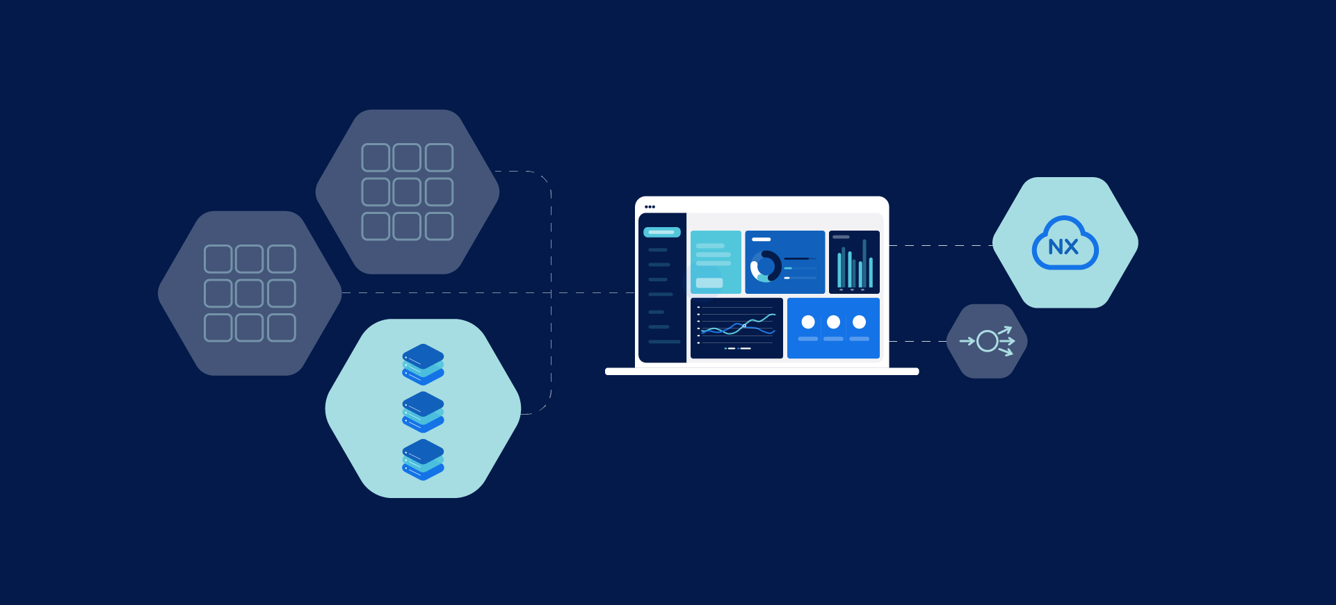
Here’s a diagram that illustrates a typical 2-tier web and DB setup on CloudNX. A LB is deployed and is distributing inbound traffic addressed to the load-balanced IP to two web servers deployed into different AZs. The connection from the LBs to the web servers is on the public network. There are two DB servers split between the AZs, and the connection between the web and DB servers is in a private network.
Keen eyed observers will notice that the private network is extended between the AZs, implying some degree of shared L2 failure domain. Actually, this is tunnelled across a L3 underlay network to reduce risks from shared L2 failure modes.
This could be deployed across multiple DCs using the round-robin DNS approach outlined earlier, but please remember that private Vlans can’t yet be extended between DCs – we’re working on that!
The bottom line is that CloudNX can give you the infrastructure you need, however big and complex your project is.
Looking for more interesting reads? Check out the rest of our server-focused blogs! And if you ever need any help with your products, our support team is here to answer your questions 24/7.