
Updated on 18 Jun 2025
We’ve recently spotted quite a few of our Cloud Server customers struggling with IPsec site-to-site VPN configuration. This is a super complex topic, so we thought we’d provide an overview of the different tech involved, and walk you through the deployment of an example site-to-site VPN connecting private networks in two Cloud data centres.
An overview of IPsec
Firstly, let’s have a quick look at exactly what IPsec means. IPsec is a suite of protocols that work together, in order to provide authentication and encryption on top of IP. In short, it helps to secure data shared over public networks.
The most common use case for IPsec is to provide VPN services and there are two common deployment modes for IPsec VPNs worth noting. These are:
- Remote access VPNs
- Site-to-site VPNs
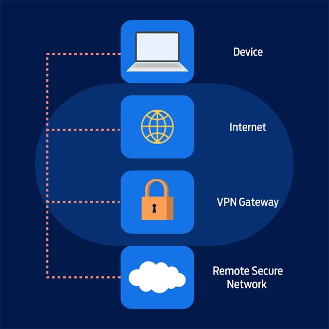
Remote access VPNs
As you might guess from their name, remote access VPNs are used where remote clients need to securely connect to a central site. For example, staff working from home would use remote access VPNs to connect to the office network.
This is typically a 1-to-1 VPN connection, where each user establishes an on-demand connection to the VPN gateway, so they can access services in the remote or central LAN on demand.
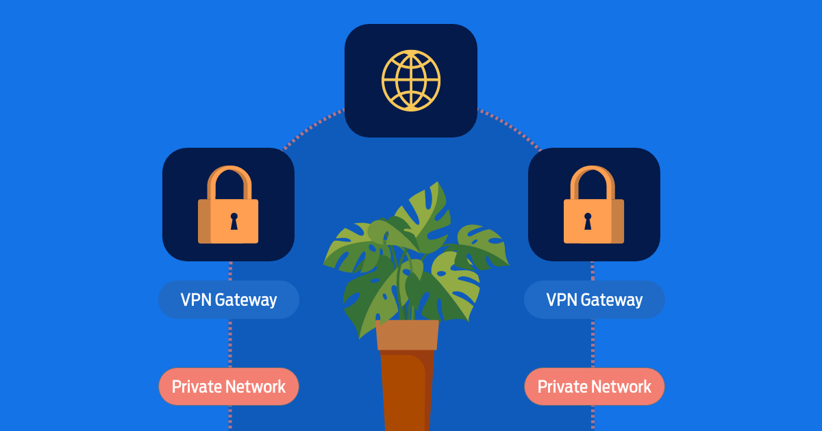
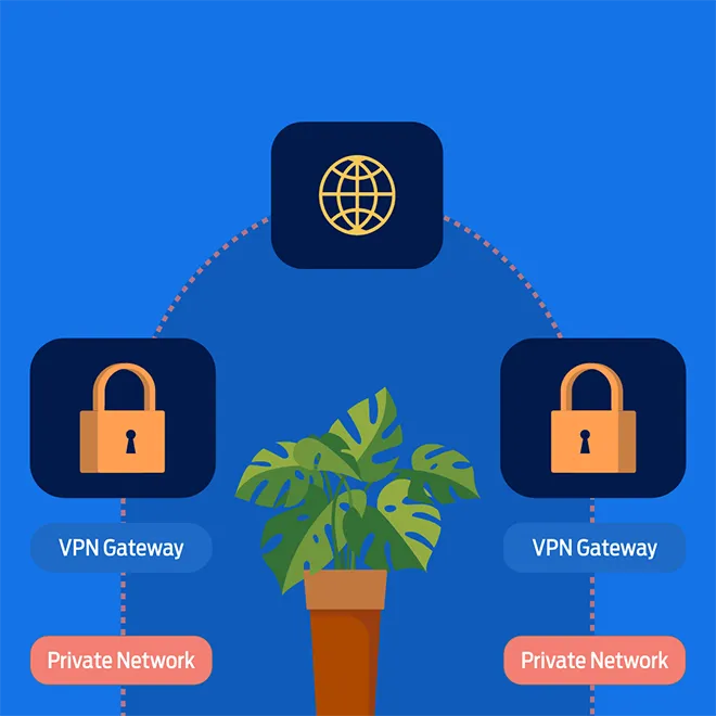
Site-to-site VPNs
By contrast, site-to-site VPNs are used when two or more networks need to be securely connected. Here are a few different scenarios where site-to-site VPNs would be used:
- Connecting on-premise networks to the cloud
- Connecting disparate cloud networks together
- Connecting branch offices to the central office or DC
These VPNs can be viewed as an “always-on” connection. This is because, typically, the VPN tunnels are established dynamically when one of the VPN gateways receives traffic from the local LAN, with a destination of the remote LAN which is reachable across the tunnel.
It’s worth noting that we’re using “gateway” here as a generic term to describe a device that performs IP routing and IPsec VPN termination – like a firewall, router or server.
Benefits of site-to-site VPNs
Site-to-site VPNs provide a secure connection between networks, which makes them invaluable for businesses with multiple offices. Here are some additional benefits of site-to-site VPNs:
- Improved access control because access rules are simpler to define. Site-to-site VPN users are all ‘internal’ users, which means that access control rules can simply block any traffic originating from outside the network to keep resources strictly internal.
- Better security due to the effectiveness of access control. Plus, since all traffic is encrypted when flowing over a site-to-site-VPN, business data is better protected.
- Simplified network architecture. Organisations typically use internal IP address ranges for devices within their LANs, but these have to be converted to external IP addresses to be accessible from the public internet. However, all site-to-site VPN users are ‘internal’ users, which means that you can stick to just using internal IP addresses.
Now at this point, it’s important for us to say that cryptography in general, and IPsec in particular, is a deep and complex topic that ideally needs its own article to explain. Instead, we’ll touch on some of the key elements at a high level and show you some example configurations on Ubuntu.
Internet Key Exchange
This is where Internet Key Exchange comes in. When two VPN gateways try to build a tunnel, they exchange messages, like the encryption and authentication parameters. During this negotiation process, the gateways try to agree on a common set of protocols that will then govern the secure channel as it’s configured.
This exchange of keys takes place via the Internet Key Exchange protocol, also known as IKE. There are two different versions of IKE to know about – IKEv1 and IKEv2. IKEv2 is a more advanced, secure protocol, and that’s what we’re going to focus on here.
In IPsec negotiation, the peer who initiates the session is called the initiator, and the peer who responds is called, you guessed it, the responder.
There are two phases to this IPsec session negotiation, which are (predictably) called IPsec Phase 1 and Phase 2. After a phase has successfully been completed, there’s a corresponding Security Association, or SA. If you’re troubleshooting a problematic IPsec connection, it’s helpful to know whether the problem is occurring in Phase 1 or Phase 2.
Phase 1
The core purpose of Phase 1 is creating a secure channel for exchanging IKE messages. In other words, Phase 1 essentially ensures that Phase 2 can go ahead securely.
Phase 2
In Phase 2, the peers actually exchange keys. These will be generated based on the pre-shared key or certificates, and this is where parameters like Diffie Hellman group will be specified, if Perfect Forward Secrecy (PFS) is used.
The different deployment modes
There are two different deployment modes for IPsec site-to-site VPNs, route based (AKA Virtual Tunnel Interface) and policy based.
With route-based IPsec, the VPN gateway has a virtual tunnel interface (or VTI), and you can define what traffic goes over the VPN using routes. You configure a route for the remote network with a next-hop of the VTI, and all traffic following that route will be sent over the tunnel.
Meanwhile, with policy-based IPsec you define what traffic goes over the VPN using a policy that defines the encryption domain. This policy contains the local and remote networks. Only traffic that matches this policy will be encrypted and sent over the VPN. This approach implies a point-to-point connection – in other words, you can connect a maximum of two sites together.
Here are some of the key differences to bear in mind:
Route-based IPsec
- The VPN gateway has a virtual tunnel interface, and any traffic routed via this interface is sent over the VPN tunnel
- Supports hub-and-spoke topologies, e.g. multiple sites
- Supports dynamic routing
- Less widely supported
Policy-based IPsec
- The VPN gateway will only permit traffic across the VPN tunnel if it matches the encryption domain
- Only supports point-to-point connection, e.g. two sites
- Widely supported across different vendors and operating systems
Configuring cloud servers as IPSec site-to-site VPN gateways
In the example we’re using here we’ll configure the following topology:
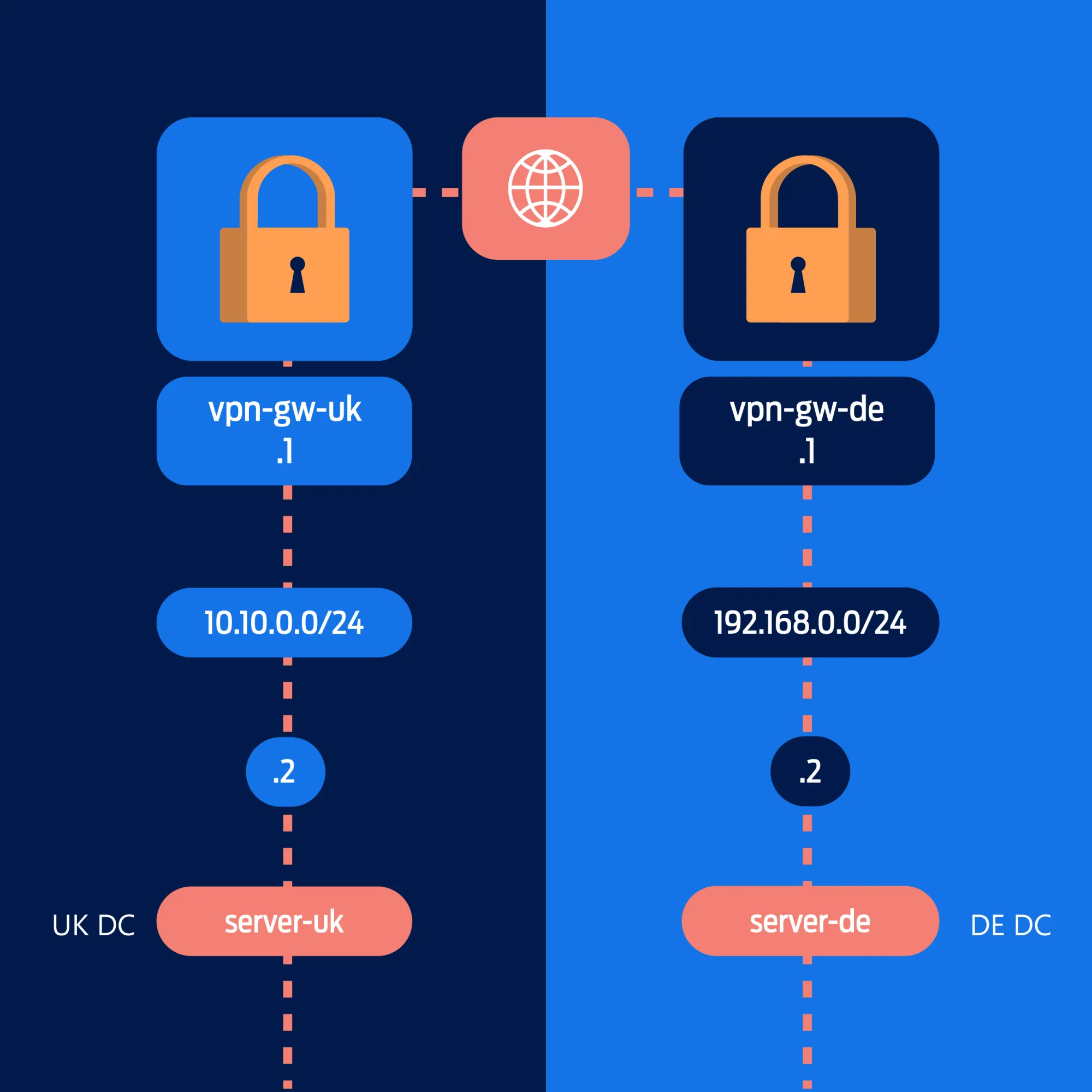
The goal here is to provide secure connectivity between two private networks, across a public network. In this case, one private network is in a UK DC, and another is in a German (DE) DC.
Each network will comprise of two servers, both of which are addressed onto a private network. One server in each network will be configured as the VPN gateway.
For this example setup, we’ll be using Cloud Servers running Ubuntu 22.04 and installing software called strongSwan for the IPSec VPN functionality.
Windows Routing and Remote Access does natively support IPSec/IKEv2, but the Linux strongSwan implementation is more robust – plus it’s easier to install and operate.
While this use case of providing secure routing between private networks in different Cloud DCs is valid, it’s more common that customers want to connect their Cloud private network to an on-premise router or firewall, another cloud provider or some other service provider.
This is generally where the complexity of IPsec becomes a problem. The specifications made by IPsec profiles have to match, and different vendors tend to have their own implementation quirks.
Firewall configuration
Over in the CloudNX control panel, you can create and modify security policies, and allocate them to servers. You’ll need to ensure that VPN traffic (UDP ports 500 and 4500, and IPSec) is permitted.
In this example, the same policy is bound to both VPN gateways, so we’ll reference both public IPs in a single policy.
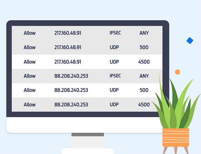
If you’re using a local firewall like iptables, don’t forget to permit the VPN traffic there too!
Server configuration
But before we start with the VPN gateways, we’re going to configure the private network interface on the uk-server and de-server.
Note that the CloudNX panel takes care of adding the interface to your cloud server, but you still need to configure it with an IP address and a subnet mask.
While we’re at it, we’ll add the static routes so that the servers know to reach the remote private network via their local VPN gateway (otherwise they would follow their default route out of their public interface).
As we’re using Ubuntu 22.04 here, we can use netplan to configure the private network interface. Create a new file /etc/netplan/01-Private_network.yaml, and set the relevant IP address for each server in the “addresses” field.
de-server
network:
  ethernets:
    ens224:
      dhcp4: false
      addresses: [192.168.0.2/24]
      routes:
        to: [10.10.0.0/24]
        via: [192.168.0.1]
  versions: 2
uk-server
network:
  ethernets:
    ens224:
      dhcp4: false
      addresses: [10.10.0.2/24]
      routes:
      - to: 192.168.0.0/24
        via: 10.10.0.1
  versions: 2
Next, you need to activate the private network interface and static route with netplan.
netplan applyAt this point, it’s a good idea to test that the private network is working properly by pinging the local VPN gateway.
root@de-server:~# ping 192.168.0.1 -c 2
PING 192.168.0.1 (192.168.0.1) 56(84) bytes of data.
64 bytes from 192.168.0.1: icmp_seq=1 ttl=64 time=0.496 ms
64 bytes from 192.168.0.1: icmp_seq=2 ttl=64 time=0.410 ms

--- 192.168.0.1 ping statistics ---
2 packets transmitted, 2 received, 0% packet loss, time 1012ms
rtt min/avg/max/mdev = 0.410/0.453/0.496/0.043 ms
root@de-server:~#
root@uk-server:~# ping 10.10.0.1 -c 2
PING 10.10.0.1 (10.10.0.1) 56(84) bytes of data.
64 bytes from 10.10.0.1: icmp_seq=1 ttl=64 time=0.625 ms
64 bytes from 10.10.0.1: icmp_seq=2 ttl=64 time=0.429 ms
--- 10.10.0.1 ping statistics ---
2 packets transmitted, 2 received, 0% packet loss, time 1030ms
rtt min/avg/max/mdev = 0.429/0.527/0.625/0.098 ms
root@uk-server:~#After this, your servers should be good to go! Next up, we’ll log in to the VPN gateways and install strongSwan, as well as any related packages.
sudo apt-get update && sudo apt-get upgrade

sudo apt install strongswan strongswan-pki libcharon-extra-plugins libcharon-extauth-plugins libstrongswan-extra
-plugins libtss2-tcti-tabrmd0 -y
Now the strongSwan service should be running. But remember that the service is actually named IPsec – and check that the IPsec service status is active (running).
systemctl status ipsecIt’s time to enable IP routing – edit the file /etc/syctl.conf and add the following entries:
net.ipv4.ip_forward=1
net.ipv6.conf.all.forwarding=1
net.ipv4.conf.all.accept_redirects = 0
net.ipv6.conf.all.accept_redirects = 0
Then you’ll need to reload the edited sysctl.conf file.
sysctl --systemThe strongSwan configuration is stored in /etc/ipsec.conf – and we’ll rename that file in case we want to refer or revert to the original later on.
mv /etc/ipsec.conf /etc/ipsec.conf.bakNow we’ll create a new /etc/ipsec.conf on each VPN gateway. The configuration below specifies IKEv2 with pre-shared-key based authentication, and AES256-SHA256-DH group 14 in Phase 1, and AES256-SHA512-DH group 14 in Phase 2.
You can choose other cipher suites as needed, but remember that both sides have to agree on a common set of cipher suites!
First up is the vpn-gw-uk configuration. Note that the left side refers to the local configuration and the right side refers to the remote configuration.
config setup
    cachecrls=yes
    strictcrlpolicy=yes

config setup
        charondebug="all"
        uniqueids=yes
        strictcrlpolicy=no

conn vpn-to-de
        keyexchange=ikev2
        authby=psk
        left=88.208.240.253
        leftsubnet=10.10.0.0/24
        right=217.160.48.91
        rightsubnet=192.168.0.0/24
        compress=no
        dpdaction=restart
        dpddelay=30s
        esp=aes256-sha256-modp2048
        ike=aes256-sha512-modp2048
        ikelifetime=3h
        lifetime=1h
        keyingtries=%forever
        keylife=3600s
        rekeymargin=540s
        authby=secret
        auto=start
Whereas on vpn-gw-de server, we’ll use an identical config but invert the left/right parameters. Like this:
config setup
    cachecrls=yes
    strictcrlpolicy=yes

config setup
        charondebug="all"
        uniqueids=yes
        strictcrlpolicy=no

conn vpn-to-uk
        keyexchange=ikev2
        authby=psk
        left=217.160.48.91
        leftsubnet=192.168.0.0/24
        right=88.208.240.253
        rightsubnet=10.10.0.0/24
        compress=no
        dpdaction=restart
        dpddelay=30s
        esp=aes256-sha256-modp2048
        ike=aes256-sha512-modp2048
        ikelifetime=3h
        lifetime=1h
        keyingtries=%forever
        keylife=3600s
        rekeymargin=540s
        authby=secret
        auto=start
That’s it, you’re done! Let's check the status of the VPN with 'ipsec status':
root@vpn-gw-de:~# ipsec status
Security Associations (1 up, 0 connecting):
  vpn-to-uk[11]: ESTABLISHED 2 minutes ago, 217.160.48.91[217.160.48.91]...88.208.240.253[88.208.240.253]
  vpn-to-uk{41}:  INSTALLED, TUNNEL, reqid 1, ESP SPIs: c02908e1_i cd0798e0_o
  vpn-to-uk{41}:    192.168.0.0/24 === 10.10.0.0/24
As you can see, the tunnel is successfully established. Now to complete the picture, we’ll traceroute from the de-server to uk-server, confirming that the path is via the VPN.
root@server-uk:~# traceroute 10.10.0.2
traceroute to 10.10.0.2 (10.10.0.2), 30 hops max, 60 byte packets
 1  192.168.0.1 (192.168.0.1) 0.288 ms 0.243 ms 0.220 ms
 2  10.10.0.1 (10.10.0.1) 19.988 ms 20.192 ms 20.292 ms
 3  10.10.0.2 (10.10.0.2) 20.394 ms 20.519 ms 20.489 ms
Performance testing
After installing iPerf on de-server, we can run it in server mode with 'iperf -s' and connect to that with iPerf in client mode on uk-server with 'iperf -c 10.10.0.2'.
root@server-uk:~# iperf -c 10.10.0.1
------------------------------------------------------------
Client connecting to 10.10.0.2, TCP port 5001
TCP window size: 85.0 KByte (default)
------------------------------------------------------------
[  1] local 192.168.0.2 port 47750 connected with 10.10.0.1 port 5001
[ ID] Interval		Transfer		Bandwidth
[  1] 0.0000-10.0614 sec	452 MBytes		377 Mbits/sec
So, we get 377 Mbit/s for TCP traffic which is good considering the public network for cloud servers is limited to 400 Mbit/s (bare metal servers get 1 Gbit/s). These are M-Size cloud servers with 2 vCPU and 2GB RAM, so they’re not especially advanced.
However, if you’d run the iPerf between cloud servers in the local private network, you could expect a speed more like 8 Gbit/s.
We know we’ve only scratched the surface of IPsec VPNs in this article, but hopefully you can come away with a helpful overview, as well as some sample configurations to get a site-to-site VPN up and running through your CloudNX control panel.
Looking for more good Cloud reads? There's a whole bunch over in the Cloud section of our blog, including how to build highly-available web applications on CloudNX!